Hey the longest uppercase title appeared around here! It's for a small nice Arduino module I came across recently. I was so excited to try the new module that I wired it to Arduino and immediately uploaded the sketch. While uploading I heard a strange sound, like frying oil…

It was the led! I disconnected power instantly and started reading the documentation to understand what was going on. Finally, I read the seller advice:
"THIS MODULE DOES NOT INCLUDE CURRENT LIMITING RESISTORS. This allows the module to be used with a range of supply voltages but you must drive the LED's via an appropriate current limiting resistor otherwise damage to the LED's will occur. "
Gasp! And it was written in capital letters!
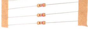
With some pain I looked in my store and found some 270 Ohm resistors which fitted our case. A new trial and hop! Now it works fine and the module is still operational! Wow!
Here is the sketch provided by the seller. Clearly, this module has been much appreciated also by my children. "An interesting piece at last!" they said.
/* FILE:    ARD_RGB_LED_MODULE_HCARDU0021_Example.pde
   DATE:    04/07/12
   VERSION: 0.1

This is a simple example of how to use the HobbyComponents RGB LED
module (HCARDU0021). The module has 3 separate LED's (Red, Green &
Blue) which can be individually driven by applying a voltage to
the appropriate module pin.
This example uses the standard Arduino analogWrite (PWM) function
to cycle through the full range of colours this module is capable
of producing.
Please be aware that this module does NOT include current
limiting resistors and therefore you should not connect this
module directly to the Arduino DIO pins.

SENSOR PINOUT:

PIN 1: GREEN LED +Ve
PIN 2: RED LED +Ve
PIN 3: BLUE LED +Ve
PIN 4: GND

You may copy, alter and reuse this code in any way you like but
please leave reference to HobbyComponents.com in your comments
if you redistribute this code.
THIS CODE MAY NOT BE USED IN ANY FORM BY OTHER EBAY SELLERS.*/


#define BLUE_LED_DIO 11   /* DIO pin for driving the BLUE LED */
#define RED_LED_DIO 9     /* DIO pin for driving the RED LED */
#define GREEN_LED_DIO 10  /* DIO pin for driving the GREEN LED */

/* Initialise serial and DIO */
void setup()
{
  /* Configure DIO pins used by the analogWrite PWM function  */
  pinMode(BLUE_LED_DIO, OUTPUT);
  pinMode(RED_LED_DIO, OUTPUT);
  pinMode(GREEN_LED_DIO, OUTPUT);
}

/* Main program loop */
void loop()
{
  int k;

  /* Slowly reduce the red LED's intensity and at the same time
     increase the green LED's intensity */
  for (k = 0; k <=255; k++)
  {
    analogWrite(RED_LED_DIO,255 - k);
    analogWrite(GREEN_LED_DIO, k);
    delay(10);
  }

  /* Slowly reduce the green LED's intensity and at the same time
     increase the blue LED's intensity */
  for (k = 0; k <=255; k++)
  {
    analogWrite(GREEN_LED_DIO,255 - k);
    analogWrite(BLUE_LED_DIO, k);
    delay(10);
  }

  /* Slowly reduce the blue LED's intensity and at the same time
     increase the red LED's intensity */
  for (k = 0; k <=255; k++)
  {
    analogWrite(BLUE_LED_DIO,255 - k);
    analogWrite(RED_LED_DIO, k);
    delay(10);
  }
}
No comments :
Post a Comment